Considerations for Selecting an Electronic Load
November 10, 2022 | Topics: Electronic Loads
So your test system requires an electronic load? While you are the expert on your product testing requirements and test methods, it has probably been a while since you purchased an electronic load. Today’s electronic loads have numerous features for testing electronic devices. The wide range of capabilities can pose a considerable challenge for selecting a cost-effective electronic load that can meet the requirements of current and future applications. Let us save you valuable time and suggest parameters you will want to consider when selecting an electronic load for your test needs.
Ready to Get Started? Request a Quote
Assess the power requirements for the load
Of course, the first consideration is determining how much power your load must absorb. In addition to total power, you will need to define the maximum voltage, and the maximum current your device-under-test (DUT) can supply. Your load must have power, voltage, and current input ratings that are at least equal to and preferably exceed the DUT’s output parameters.
Consider the load’s input characteristics to maximize flexibility and reduce your costs
While determining the load’s power, voltage, and current requirements are straightforward, you may want to consider how the load’s input characteristic can maximize your flexibility and potentially enable you to save money with the purchase of a lower power load. EA Elektro Automatik electronic loads have a true autoranging input characteristic which allows testing at full power over a wider range of voltage and current values. Figure 1 shows an EA load’s electronic profile compared to a conventional electronic load. The conventional electronic load, with its rectangular input characteristic, can sink maximum power only at its maximum rated voltage and current.
EA loads can absorb full power down to 33% of rated voltage. For example, a 10 kW EA electronic load with maximum voltage and current ratings at 1000 V and 30 A can absorb full power at 333 V and 30 A. An electronic load with a conventional input characteristic would have to be a 30 kW load with maximum ratings of 1000 V and 30 A to be capable of supplying 10 kW at 333 V and 30 A. As a result, autoranging can enable the use of a cost-saving, lower power load. The lower power load also has reduced cooling requirements and can save on capital costs and annual operating costs.
Similarly, if a new 10 kW DUT delivered a slightly higher voltage, you would need a new conventional input characteristic load. With EA autoranging loads, you would not need a new load as Figure 1 illustrates the availability of the extra range of the autoranging load. This means that an autoranging load can both save on the required power and can allow adapting to future requirements compared with electronic loads that have conventional input characteristics.
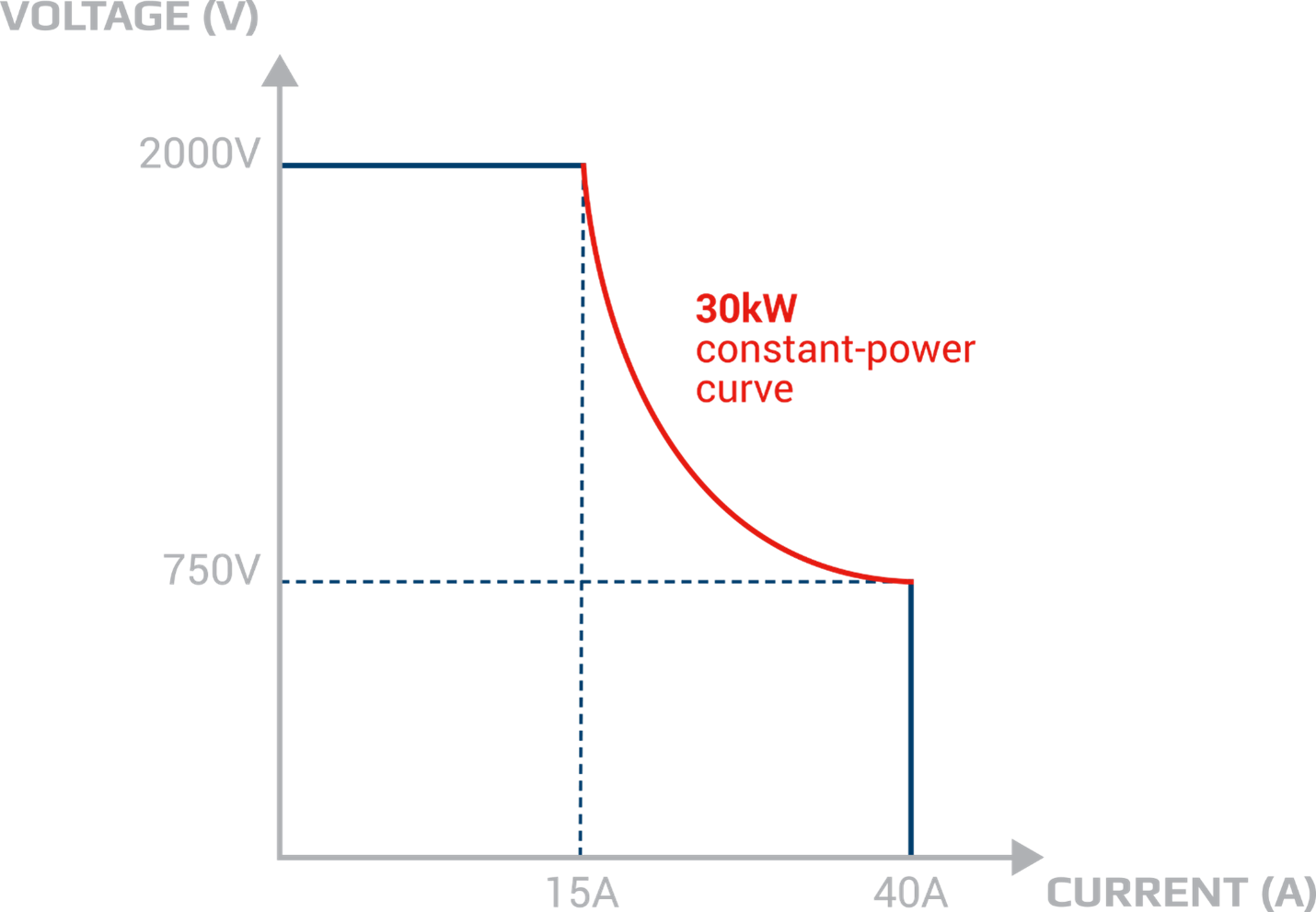
Figure 1. Input characteristic of an EA autoranging load compared with the conventional load with a rectangular output characteristic
Determine the control parameters you will need
Electronic loads can control power, voltage and current. EA loads offer additional capability and can also control resistance. Ensure that the load you select controls all the parameters that you need for testing your DUT.
Here are two instances where having the capability of controlling resistance is essential. Testing a power source will typically require a constant current mode for testing under different load conditions. Testing a charging device may require controlling voltage to determine charger response to a rising voltage. Now you need to determine performance of your DUT over a wide range of load resistances. If so, you will need your load to control resistance.
Another parameter that you will want to be aware of is how low a voltage your load must control while sinking its maximum rated current. All electronic loads have limitations on the lowest voltage at which the load can control and sink maximum rated current. Below this voltage, the sink current capacity will decrease linearly. If your test protocol requires testing your DUT’s output under low voltage conditions, ensure that the load can control at the required low voltage while sinking the required current. The load specification that defines this minimum control voltage is VMin at IMax.
Determine the type of test methods required
Will you need to test your DUT under dynamic conditions such as fast load changes or under disturbances such as noise? If you are testing a battery, a battery charger, a fuel cell, or a solar panel, you will want to simulate various test conditions. You could use an external function generator to create dynamic load conditions; however, a high-power electronic load connecting with a low power function generator adds complexity to a test setup. The function generator needs protection from the high voltage or high current that the load will be sinking. EA solves that for you by having a function generator as an integral part of the electronic load.
The built-in function generator can create custom waveforms to simulate various load conditions to stress a DUT. The function generator can produce ramp and pulse loads to test a DUTs response to dynamic load changes. Sine waves on a DC level can simulate and test the response of a DUT, such as a power supply, to noise. EA electronic loads offer a built-in function generator that can create I-V curves to simulate:
- A battery-powered device for testing battery performance
- A battery for testing on-board charger performance
- A load for a fuel cell or a solar array to test their performance.
Figure 2 shows an example of a maximum power point (MPP) curve that an EA load can simulate.
The built-in function generator allows substantial test flexibility and saves on both the need for an extra instrument, a function generator and a method to safely connect the function generator to the load.
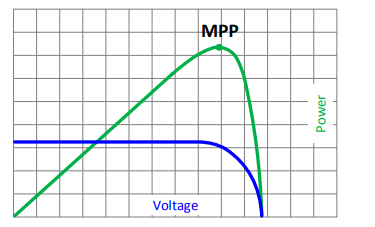
Figure 2. The built-in function generator of EA electronic loads can test solar arrays by simulating a maximum power point tracking solar inverter
Investigate savings from minimized power consumption
We can help with minimizing the power consumed from the power grid and the heat dissipated by their loads. Our EA loads offer regenerative loads which use an inverter to convert the absorbed DC power to an AC waveform and return it to the power grid. EA loads can return energy to the grid with up to 96% efficiency offering a tremendous reduction in power consumption and utility cost savings. The savings from a regenerative load can justify the higher cost over a conventional load that must have sufficient cooling to dissipate the heat from the absorbed power.
Consider the utilities required
EA loads that can absorb up to 3 kW can operate on single phase power and maintain a safe operating temperature with internal forced air cooling. Loads that are 5 kW to 15 kW require 3-phase power and use internal forced air cooling. Even EA 30 kW loads which operate on three phase power employ cooling with internal fans. In addition to fans, you can choose to use water cooling for higher power modules. Make sure you understand and prepare for the utility requirements for the electronic load that you select.
Define safety requirements for the load
Electronic loads can absorb substantial power and must support high voltages and high currents. Thus, it is important to ensure that the load is adequately protected. For example, if the load’s internal temperature reaches a high value, the heat can damage the load. Therefore, you should ensure that your load has overtemperature protection to shut down if the internal temperature reaches a dangerous level. You should also consider overcurrent, overvoltage, and overpower protection for your load. EA loads have all four protection modes.
Define your control requirements
Make sure that the load you select has the interface or interfaces you need for your application. EA loads offer an extensive set of interfaces for a wide range of applications. In addition to the standard interfaces, all the optional interfaces are field-installable modules that insert into the rear panel of the loads. Thus, you have the convenience of easily adding a new interface for a future application.
All EA electronic loads have USB and Ethernet interfaces. Also, EA loads include an optional RS-232 interface. When interfacing to a PC, the loads use standard SCPI commands for programmable control.
In the event you need a load for an industrial application, you will typically need the load to interface to a programmable logic controller (PLC). EA loads allow convenient integration into a PLC-based control system. Our loads use the Modbus command language and offer a wide range of optional interfaces for PLC control, including Modbus, CAN, CANopen, EtherCAT, Profibus, and Profinet.
In addition, you can control EA loads with an analog signal which is a standard interface. This is an isolated analog interface. Not all loads have an isolated analog interface to separate instrument ground from high-noise grounds in industrial applications. If you are using analog control, we recommend selecting a load with an isolated interface to avoid interference from ground noise.
If you will be manually controlling the load, ensure it has a display and manual operating controls. EA loads have touchscreen displays (see Figure2) that enable easy access to instrument settings and control functions. EA loads also offer multiple language options to enable text to be more understandable for worldwide use.
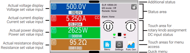
Figure 3: An EA series 10000 electronic load touchscreen
Even if you are not manually controlling your load, you should consider the convenience of having a front panel display and controls for test system development and troubleshooting. A full-color touchscreen display on EA electronic loads facilitates development and troubleshooting work.
Consider expandability for greater power handling capacity
If you have an application requiring more power than a single load can provide, you will want to select a load that can conveniently and safely enable the paralleling of multiple loads. EA has a master-auxiliary operating mode so that one master load can control a set of loads. Furthermore, EA loads have a Share-Bus operating mode that ensures that all loads equally share the incoming power. The Share-bus feature protects each load from absorbing an excessive quantity of power and becoming damaged. EA offers a range of turnkey DC power racks and cabinets that come wired and ready for use with fully integrated safety systems, compliant with UL508/NFPA-79. Each power rack includes door interlocks and individual breakers for each supply or load, plus an emergency stop on the cabinet door. With EA loads, you can build a system of loads that can sink up to 1.92 MW.
Select your software environment
For automated testing, you can program an electronic load using standard programming languages such as versions of C or Python or a graphical programming language such as National Instruments’ LabView™. If you prefer not to code, EA Elektro Automatik offers Power Control Software to control its instruments, including the electronic loads. The software enables control of the load, creation of control sequences, and execution of test schemes for battery testing, fuel cell testing, automotive standards tests, and solar panel tests. The EA Power Control Software enables fast development of automated control programs using EA loads.
Now you are ready to select your electronic load
Once you have assessed your needs based on what we have recommended, you are ready to select an electronic load or loads that will cost-effectively meet your requirements. Take a look at our EA Elektro Automatik Electronic Load Selection Guide, which offers numerous models and systems of electronic loads.
If you have any further questions after reviewing the Load Selection Guide, contact us at sales@elektroautomatik.com or 858-836-1300. Our Application Engineers can assist you in finding the right electronic load with the features you need.