Efficiently and Easily Test Fuel Cells
June 01, 2024 | Topics: Electronic Loads, Fuel Cell
One fuel cell type at the cornerstone of modern clean energy solutions is hydrogen fuel cells. They convert chemical energy from fuels into electrical energy through electrochemical reactions. Unlike conventional combustion-based power generation, fuel cells produce electricity with higher efficiency and significantly lower emissions, making them vital for sustainable energy systems.
However, much like traditional power sources, fuel cell systems require extensive testing to ensure that they deliver the cell performance, durability, and longevity necessary for the intended use case. By creating a rigorous testing program, you can ensure that your designs meet regulatory standards while also optimizing product quality.
In the following, fuel cell testing best practices are outlined. You’ll learn how to improve your testing protocols through robust tools and discover step-by-step instructions for evaluating the capabilities of your designs.
Ready to Get Started? Request a Quote
Why Fuel Cell Testing Is Crucial
Testing solutions allow you to evaluate the operational characteristics of fuel cell technology. Through comprehensive testing, you can verify that every single cell operates safely under different conditions, including high temperatures and extreme back pressures. It also ensures compliance with laws and industry standards, which is crucial for consumer confidence and market approval.
Additionally, testing services enable you to better understand the longevity and efficiency of a fuel cell stack. You can identify degradation mechanisms and the impact of numerous operating conditions on product lifespan. In turn, you’ll be able to use these insights to implement targeted changes and improve your design’s quality.
Key Considerations for Fuel Cell Testing
There are several types of fuel cells, each with unique characteristics and testing requirements:
- Proton Exchange Membrane Fuel Cells (PEMFCs): Commonly used in transportation and require tests for rapid startup and dynamic load changes
- Solid Oxide Fuel Cells (SOFCs): Need high-temperature testing and durability assessments under thermal cycling
- Alkaline Fuel Cells (AFCs): Require tests for purity of hydrogen and oxygen to prevent contamination
- Phosphoric Acid Fuel Cells (PAFCs): Suitable for large-scale stationary applications requiring efficiency and heat recovery testing
The best fuel cell test systems are capable of meeting the testing needs of multiple types of cells. For instance, EA Powered provides dynamic testing equipment that allows you to test a wide range of variables, including cell voltage, conductivity, energy storage, power range, flow control, humidification, and more.
Now, it’s helpful to take a closer look at some of the common challenges in fuel cell testing, all of which our testing and simulation equipment helps you solve.
Common Challenges in Fuel Cell Testing
Thoroughly testing fuel cells while simultaneously maintaining safety can be quite challenging. One of the most notable hurdles is the complexity of the reactions within the fuel cells. Numerous variables can influence these electrochemical reactions, making consistent and reproducible testing difficult.
Fuel cells are also sensitive to environmental conditions such as temperature and humidity, requiring precise control during testing. For that reason, you’ll need a humidifier and a high-performance thermostat to ensure that conditions remain consistent during testing.
Another challenge involves measuring material degradation, which requires long-term testing. Running repeated, lengthy tests can be time-consuming and expensive. Lastly, you’ll need a way to organize all of this data so that you can analyze it and evaluate cell performance.
Fortunately, EA Powered and our suite of simulation tools can help you mitigate most of these variables. You can create ideal testing environments, precisely manipulate single variables, and set up automation protocols to save time and resources. By accelerating the testing process while mitigating the risk of errors, we help you perform more reliable and trustworthy evaluations.
Measuring Fuel Cell Resistance
Figure 1 shows a simplified model of a fuel cell. One of the most important parameters of fuel cell efficiency is its ohmic resistance which determines power loss in the fuel cell’s output. The recognized techniques to measure the fuel cell’s resistance involve a perturbation in which a ΔI in the load on the fuel cell is created; and the resulting ΔV (or ΔU) is measured. The fuel cell resistance is then ΔV/ΔI. The ΔI can be large, as in the current interrupt method, in which the current is momentarily turned off so that the voltage drop across the fuel cell resistance is 0 V. The other method induces a small AC perturbation on the cell and makes voltage measurements at one or multiple frequencies. The two methods produce different results. The current interrupt method produces a higher resistance than the high frequency technique resulting from an additional voltage generated in the porous electrodes due to the large perturbation. The AC perturbation technique minimally disturbs the fuel cell. We feel this method for determining fuel cell resistance gives results that more closely determine the actual fuel cell resistance.
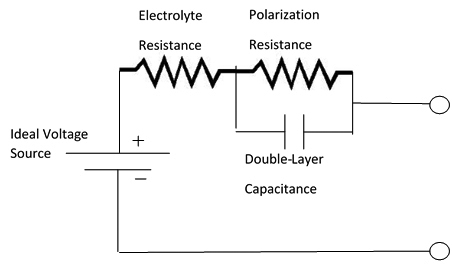
Figure 1: Simplified model of a fuel cell.
So how do you create the ΔI needed to characterize the fuel cell? You need an electronic load and the ability to vary its constant current output with an AC signal of varying frequency. You could connect the load and a waveform generator together. Waveform generators are generally low power devices, so you would have a problem testing a fuel cell stack containing a number of fuel cells. You could connect the waveform generator through a bias-T to the electronic load; but, bias-T’s are low power components used primarily for RF applications. Connecting a low power waveform generator to a high-power electronic load is a challenge. We solve that challenge with our ELR electronic loads by integrating the waveform generator into the load. You do not have to worry about external connections and protecting a waveform generator from damaging high power. The waveform generator outputs sine waves, triangle waves, square waves, trapezoidal waves, ramps, and arbitrary waveforms. With the ELR load, you can create any type of dynamic load including a sinusoidal perturbation on a DC current sink for fuel cell resistance characterization.
In addition, the ELR load, with its internal waveform generator can subject the fuel-cell-under-test to a wide range of dynamic load variations for both performance and durability testing. The load can stress a fuel cell with large step load changes at varying duty cycles.
Simulating a Fuel Cell for Realistic Inverter or DC-DC Converter Testing
Now that the fuel cell is characterized, the PSB-series power supplies, which also have a built-in waveform function generator, can simulate the output of a fuel cell. Using the simulated fuel cell, an inverter for a device such as a standby power source or a DC-DC converter for an automotive vehicle can be tested under the most realistic conditions. Just use the Function Generator Application in the Elektro Automatik Power Control Software. Enter the key voltage and current parameters, and the Function Generator App enables the PSB power supply to emulate the output of your fuel cell stack. Figure 2 shows the window for the Fuel Cell table which shows the fuel cell characteristic V-I curve and defines the fuel cell output. At maximum voltage, fuel cell output is dominated by electro-kinetic effects. In the central part of the curve, the linear, ohmic resistance of the fuel cell determines the output characteristics. At the high current-low voltage portion of the curve, the exponential characteristic is defined by energy being consumed at a faster rate than hydrogen and oxygen can diffuse to the anode and cathode to supply energy.
The simulated fuel cell output can test inverter or DC-DC performance as these loads draw both low current and high current. The results indicate how well the loads can maintain their output under the varying voltage of the fuel cell. Fortunately, you do not need a complex test setup with an external variable resistance for testing inverters and DC-DC converters. All you need is a PSB-series power supply.
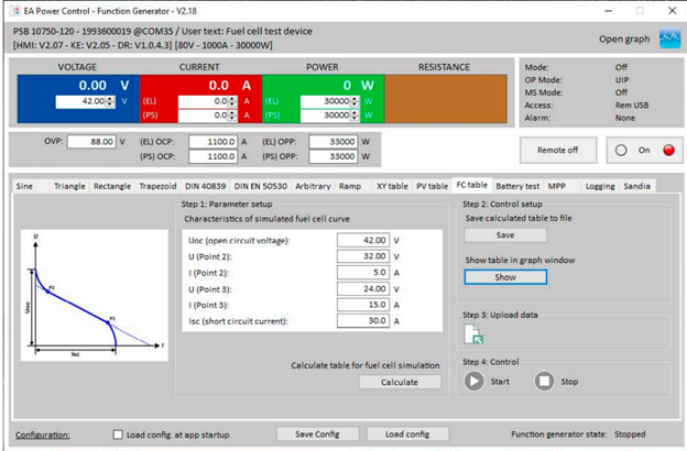
Figure 2. Function Generator application with the Fuel Cell table displayed
Advanced Tools and Equipment for Fuel Cell Testing
Simulators are just one of the modern testing solutions that you can use to support your fuel cell testing protocols. Other advanced tools include:
- Fuel Cell Test Stations: Integrated systems that control and measure temperature, pressure, humidity, and gas flow rates
- Electrochemical Impedance Spectroscopy (EIS): Analyzes electrochemical processes within the fuel cell and can diagnose issues like catalyst degradation
- Load Banks: Simulate the electrical load on the fuel cell
- Environmental Chambers: Provide controlled environments for testing cells under different temperatures and humidity conditions
Generally, you’ll need a combination of these and other testing tools to thoroughly evaluate your design’s capabilities. Incorporating these technologies into your analytical strategy allows you to unlock numerous benefits, including:
Accuracy
High-precision instruments provide your team with reliable data for evaluating cell performance and identifying issues. Maintaining control over critical variables like temperature and humidity is especially important for ensuring that your results are trustworthy.
Efficiency
Automated testing tools streamline your research and development process. You can reduce time and labor costs while at the same time accelerating speed to market.
Data Analysis
Advanced software tools facilitate real-time data collection and analysis, enabling quick decision-making and optimization. Instead of sifting through mountains of information, your team can seamlessly transform data into easy-to-digest visuals.
Reproducibility
Consistent testing conditions foster reproducibility, which is essential for validating results and improving fuel cell designs. When you set the stage for reproducible results, you can also engage in redundancy testing to verify product quality.
Best Practices for Efficient Fuel Cell Testing
Now that you understand the importance of fuel cell testing, explore these essential best practices as they pertain to three key facets of the testing process:
Setting Up the Testing Environment
First, you’ll need a well-designed testing environment so you can keep up with accuracy and safety. Maintain stable temperature, humidity, and pressure conditions throughout each evaluation process so that these variables do not skew your results.
Additionally, you’ll need fuel cell test stations with precise electronic load control to thoroughly evaluate your design’s performance. Regularly calibrate this and other equipment to promote accuracy.
Perhaps most importantly, you must implement safety protocols to handle gases and high temperatures while protecting your team from any testing risks. Train them on the use of personal protective equipment and any other relevant items.
Standardizing Testing Procedures
Next, you’ll need to create standardized procedures to ensure that your results are reliable, consistent, and comparable. Develop and adhere to a set of standardized testing protocols for each type of fuel cell, and keep detailed records of testing procedures and conditions so you can identify any variability.
Make sure your staff has received adequate training on protocols and safety procedures. Create a handbook with reference materials so they can refresh their memory on important processes as needed. As protocols change, make sure to administer additional rounds of training to bring them up to speed on the newest requirements.
Utilizing Software for Data Collection and Analysis
After you’ve completed your tests, it’s time to dig into the data. Use software to automatically record information from your testing equipment. The best platforms will document and organize everything, which can expedite the evaluation process and help your team better understand the outcome of each experiment.
Your team should integrate data from different tests to obtain a holistic view of performance, longevity, and durability. Remember, each evaluation round provides a piece of the puzzle. Therefore, it’s important to build comprehensive protocols so you can accurately explore all the performance and longevity elements of your design.
Step-by-Step Guide to Fuel Cell Testing
To achieve safe and efficient fuel cell testing, you must follow the proper procedure. Take these three important steps to give yourself the best chance of obtaining your desired outcome:
Preparing the Fuel Cell for Testing
Getting your cells ready for testing is critical for accuracy and safety. Thoroughly inspect the fuel cell for any physical damage or defects. If anything appears off or unusual, do not use the item, as it could suffer a catastrophic failure. Instead, postpone testing until you can obtain a replacement.
Next, precondition the fuel cell by running it at low loads to stabilize its performance. The precondition time will vary based on the type and size of the cell. Make sure to document what steps you take during pre-conditioning so that you can repeat the process with future power sources.
Finally, set the fuel cell up to your test station. Ensure that all connections are secure and leak-free. Something as minor as a loose connection could skew your test results or create hazardous conditions for your team.
Conducting the Tests
After you have conditioned the item and set up your environment, you are ready to start running tests. At a minimum, you should be conducting three different types of evaluations, including:
- Performance Testing: Measure power output, efficiency, and response to load changes
- Durability Testing: Run the fuel cell for extended periods to assess long-term performance and degradation
- Safety Testing: Evaluate the fuel cell’s response to extreme conditions and potential failure modes
Document your settings during each cycle of evaluation. You’ll need to check that the conditions and testing constraints are identical during each round. Even minor changes to humidity, temperature, or load could skew your results and lead to discrepancies.
Analyzing and Interpreting the Results
Finally, you are ready to analyze the results of your testing processes. Carefully review all of the data you collected and note any deviations from your expectations. Next, identify performance trends and degradation patterns. Compile detailed reports that include:
- Test procedures
- Data
- Analysis
- Recommendations for product improvement
Make sure to maintain comprehensive records of each testing cycle, too. This way, you can compare the performance of new designs to previous iterations and ensure that your alterations are improving product output. Focus on incremental design changes so that you do not inadvertently push the product out of safe operating thresholds.
Save on extra and higher power supplies and loads
Both the PSB power supplies and the ELR electronic loads autorange to offer a wide span of voltage outputs/inputs and current outputs/inputs. Autoranging allows the supply or the load to output (consume) a wide output span of voltage and current at full power. Figure 3 shows the output characteristic of an autoranging power supply compared with the characteristic output of a fixed range power supply. For example, a fixed range, 1 kW supply could have a maximum output of 100 V at 10 A; while, a 1kW autoranging power supply could have a 200 V output at 5 A and a 10 V output at 100 A. Thus the autoranging supply can provide a much wider range of voltage and current. If you need more than 100 V or 10 A, you would need a higher wattage, fixed range power supply. That’s more expense and a larger instrument. With autoranging, you have the flexibility to address more test applications with a single supply. Using fixed range supplies could require a different power supply for different tests. Think about autoranging when you need a new power supply or load.
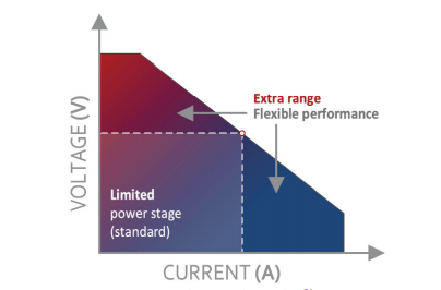
Figure 3. An autoranging power supply with wider voltage and current output compared with a fixed range output power supply
Real-World Applications
Manufacturers use fuel cells in a wide range of applications. Leading automakers have successfully tested and deployed fuel cell vehicles (FCVs), such as the Toyota Mirai. While these designs are not readily available on the open market yet, they demonstrate the viability of fuel cells in transportation.
Stationary power generation companies like Bloom Energy have deployed SOFCs for reliable, efficient stationary power generation in multiple industries. Portable fuel cell systems are also entering the fold. However, these products are in the early stages of testing and development and are not yet widely available.
Source Your Fuel Cell Testing Equipment From EA Powered
The equipment you use for fuel cell testing will have a huge impact on the reliability and accuracy of your evaluations. That’s why it is vital to source quality equipment from a reputable provider like EA Powered.
If you’d like to learn more about EA Powered and our solutions to support your fuel cell development program, schedule an online demo. When you are ready to place an order, request a quote using our website or contact our team for personalized support.