This website uses cookies so that we can provide you with the best user experience possible. Cookie information is stored in your browser and performs functions such as recognising you when you return to our website and helping our team to understand which sections of the website you find most interesting and useful. See our privacy policy.
Whether you are a seasoned engineer or are relatively new to electronic testing, it’s vital that you have the right equipment at your disposal. One of the most important devices you’ll need is an arbitrary function generator (AFG), which provides waveform creation capabilities.
In this blog post exploring AFGs, also known as arbitrary waveform generators (AWGs), you can learn everything you need to know about these wave signal generators.
Introduction to Arbitrary Function Generators
An arbitrary function generator is a sophisticated electronic instrument used to generate a wide variety of waveforms, providing you with precise control over parameters such as frequency, amplitude, and phase. Unlike traditional function generators, which are limited to producing basic waveforms like square and triangle waves, AFGs offer much better visibility.
With an arbitrary function generator, you can create complex and custom waveforms tailored to your specific requirements. You can adjust the bandwidth and engage in precise modulation.
The biggest benefit of an AFG is that you’re not limited to a predefined waveform — you can create virtually any complex waveforms imaginable. Whether you need a pulse train for digital communication testing or a modulated signal source for RF applications, an AFG can accommodate your needs.
Benefits of Using an Arbitrary Function Generator
AFGs provide many benefits over old-school analog function generators. Some specific advantages include:
Versatility
An arbitrary function generator can produce a vast array of waveforms, from simple sine waves to complex, user-defined waveforms with multiple harmonics. In other words, you can adjust the frequency range for debugging purposes, calibration, and general testing applications. The top solutions also include a robust waveform memory, which facilitates high-speed playback and test recreation.
Precision
During equipment testing, it’s vital that you maintain exceptional precision. High-fidelity solutions give you precise control over megahertz (MHz) output, sample rate, rf signal strength, memory depth, and other variables that impact testing accuracy.
If you source high-performance AFGs from a reputable provider like Elektro Automatik, you’ll find user-friendly options that complement your programmable power supplies and other equipment. Make sure to explore our full line of benchtop DC power supplies and let EA meet all of your testing needs.
Flexibility
Arbitrary function generators are indispensable tools for prototyping, research, and product development. Whether you are experimenting with new circuit designs or conducting cutting-edge research, an AFG gives you the ability to explore new ideas and iterate quickly.
You won’t be limited to standard waveforms like square waves. Instead, you can create complex signals at a wide array of MHz or GHZ ranges. You can also adjust the output frequency in real time, transitioning from burst to single or continuous output.
Waveform Synthesis With Arbitrary Function Generators
Creating a waveform with an arbitrary function generator involves several steps. First, you must choose the waveform or generation method. You can select from predefined waveforms such as sine, square, triangle, or sawtooth waves. Alternatively, you can use mathematical functions or select custom options from an existing datasheet.
Once you’ve chosen a waveform, select parameters to tailor it to your specific requirements. This may include adjusting settings such as frequency, amplitude, offset, duty cycle, and modulation.
With a high-quality solution that features an intuitive user interface, adjusting these variables becomes simple. AFGs offer unparalleled flexibility in waveform generation, allowing you to create designs such as:
Pulse Trains
A pulse train consists of a series of pulses with specific characteristics like width, repetition rate, and amplitude. AFGs can function as a pulse generator and emit trains for digital communication testing, signal generation, and modulation.
Modulated Signals
Arbitrary function generators allow you to create several types of modulated signals using techniques such as:
- Amplitude modulation
- Frequency modulation
- Phase modulation
You’ll need equipment with these capabilities if you engage in RF communication system testing or audio processing applications.
Arbitrary Waveforms
These are user-defined waveforms with arbitrary shapes and characteristics. You can either create them yourself using mathematical equations or reference external data sources. These waves play a key role in signal simulation and research applications that require precision.
Applications of Arbitrary Function Generators
There are numerous use cases for AFGs. Some common examples include:
Test and Measurement
If you engage in signal integrity testing, arbitrary function generators can help evaluate the integrity of electrical signals as they travel through a system. These devices perform frequency response analysis, which involves sweeping the frequency of the output signal to measure the system’s response over a range of settings.
Additionally, you can perform distortion testing to gauge the performance and consistency of important circuits and components. It’s possible to use these types of tests at multiple stages of product development, including early design phases and post-production quality assurance. Engaging in extensive QA through electrical testing ensures a better consumer experience.
Prototyping
Countless businesses use arbitrary function generators in circuit prototyping. Engineers can employ AFGs to simulate and test different waveform scenarios, thereby identifying potential flaws in their designs. These assessments also reveal when project teams get the circuit design right and allow them to determine how the asset will perform under different conditions.
Using AFGs in this way allows you to identify potential issues before moving to production and create the best possible solutions for your audience. Thanks to the user-friendly nature and versatility of arbitrary function generators, you can leverage these tests to accelerate iteration and design refinement processes, boosting your speed to market.
Research and Development
Lastly, arbitrary function generators are valuable tools for generating precise signals for experimentation and analysis. They enable your team to manipulate signal parameters with high accuracy, facilitating studies in areas such as:
- Communications
- Signal processing
- Instrumentation
In this way, AFGs play a pivotal role in developing new technologies and validating theoretical models.
AFGs are most effective when used with other testing tools, such as bi-directional power supply equipment. Each piece of equipment provides part of the performance puzzle. By combining data from AFGs with insights gathered through the use of other devices, you can obtain a holistic view of a piece of equipment and its functionality.
Key Features and Specifications
Before you invest in an arbitrary waveform generator, it’s important to consider some key features and capabilities, including the following:
Memory Depth
This refers to the amount of memory available for storing waveform data. The greater the depth, the longer and more complex waveforms you can generate without losing detail or fidelity.
Sampling Rate
The sampling rate determines how frequently the equipment will sample the source data to generate analog signals. Faster rates equate to better accuracy, especially at higher frequencies.
Output Resolution
The digital-to-analog converter’s (DACs) precision in converting data into analog signals will depend on its output resolution. If you need extremely precise outputs, choose a device with greater resolution.
Frequency Range
The frequency range specifies the range over which the AFG can produce waveforms. Make sure that you choose equipment that covers your project needs.
Output Amplitude
The amplitude determines the maximum voltage level at which you can produce waveforms. Consider the types of work you intend to engage in and your amplitude requirements. Then, select equipment that slightly exceeds this threshold to ensure it can adequately support your intended use.
Modulation Capabilities
Finally, explore what types of modulation capabilities a device offers. While you may not need to perform all kinds of modulation, it’s important to align the scope and functionality of your equipment with the needs of your project. For instance, if you intend to simulate real-world communication signals, you’ll need an AFG with robust modulation features.
EA and Software-Based Function Generators
Many Elektro-Automatik programmable power supplies feature a software-based function generator that can generate typical functions, such as sine, square, and triangle waves, and apply them to either the voltage or current outputs. The generator can be completely configured and controlled by using the touch panel on the front of the device, or by remote control via one of the digital interfaces.
In addition to the standard functions, users can program their own arbitrary waveforms for custom development and production testing. The arbitrary function generator allows users to create complex output functions. Arbitrary waveforms can be loaded from and saved to a standard USB stick via the USB port on the front panel, making it easy to change between different test sequences.
Ready to Get Started? Request a Quote
Arbitrary waveforms consist of up to 99 sequence points. Sequence points are more than simple amplitude values, though. A single sequence point defines an entire segment of an arbitrary waveform. The following parameters can be configured for each sequence point:
The arbitrary curve can overlay a linear progression (DC) with a sine curve (AC) whose amplitude and frequency is shaped between start and end. When both, start frequency and end frequency, are 0 Hz the AC overlay has no impact and only the DC part is effective. Each sequence point is allocated a sequence point time in which the AC/ DC curve from start to end will be generated.
In addition, users can program an arbitrary number of the 99 sequence points to run in a sequence point block and
this block can then be repeated up to 999 times or infinitely.
Here are some examples of how to create arbitrary waveforms using sequence points:
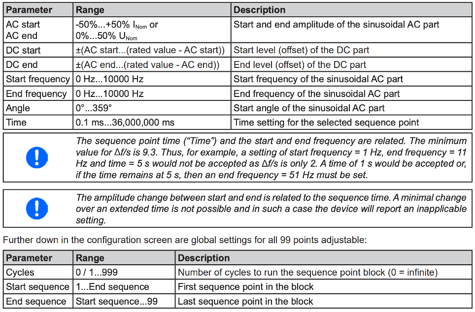
Example 1
This example uses a single sequence point to create a voltage or current ramp. The sequence point has a start and end frequency of 0 Hz. With a frequency of 0 Hz, only the DC settings apply. Because the DC end value is greater than the DC start value, the power supply will output a steadily increasing ramp.
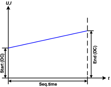
Example 2
In this example, a single sequence point is used to create the waveform shown at right. The DC values for start and end of the sequence point are the same, as is the AC amplitude. With a frequency >0 Hz a sine wave progression of the set value is generated with a defined amplitude, frequency and Y axis offset (DC values for start and end).
The number of sine waves cycles output by this sequence point depends on the sequence point time and the frequency. If the time was 1 s and the frequency 1 Hz, there would be exactly one sine wave. If the time was 0.5 s at the same frequency, there would only be a half sine wave.
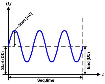
Example 3
This example is similar to example 2, but with a different end frequency. In this example, the end frequency is greater than the start frequency. Over the course of time that this sequence point is active, the period of the sine wave cycles will decrease linearly.
Example 4
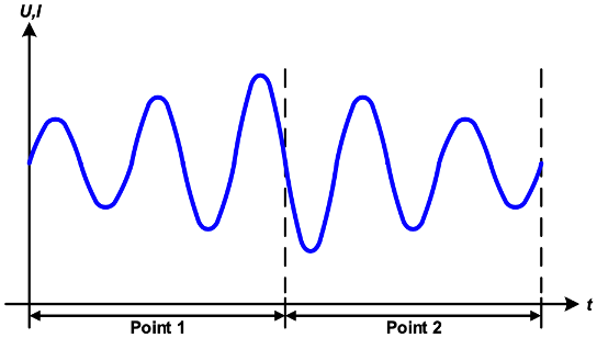
This is an example of an output waveform that uses two sequence points run consecutively. The first sine wave generates a sine wave with increasing amplitude, the second one with a decreasing amplitude. Together they produce an output that increases then decreases as shown in the figure. In order to ensure that the wave peak in the middle occurs only once, the first sequence point must end with a positive half wave and the second one start with a negative half wave.
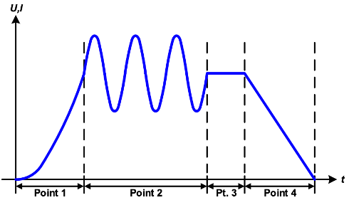
Example 5
Choosing the Right Arbitrary Function Generator
Now that you know what features an AFG offers, it’s helpful to review a few variables to consider before selecting a device:
- Application Requirements: Identify your use and ensure the device has the features you need
- Budget Constraints: Adhere to your budget by prioritizing features based on their importance to your application
- Waveform Fidelity: Evaluate fidelity by comparing generated waveforms to reference data using oscilloscope measurements
- Software Interface: Make sure the device includes user-friendly software
- Connectivity Options: Consider connections like USB, Ethernet, and GPIB to ensure seamless integration with your setup
Also, make sure to take advantage of any demo opportunities so that you can see the features of the equipment for yourself. Look beyond technical specifications and consider things like the user-friendliness of the design and the device size and footprint.
Source Your Equipment From Elektro Automatik
From autoranging DC power supplies to arbitrary function generators, EA provides a wide array of reliable, high-resolution testing equipment. Schedule an online demo or request a quote from our team.