Understanding the Factors that Determine the Accuracy of a Programmable DC Power Supply in a Circuit
January 19, 2024 | Topics: Electronic Loads, Power Supplies, Remote Sensing
Measurement accuracy is an essential specification for all manufacturing test systems. The accuracy specification is a function of all the instruments in the system and the system’s layout, including wiring selection and configuration. Determining test system accuracy must include the accuracies of any programmable DC power supplies in the test system. So, what defines programmable power supply accuracy? This blog will present the instrument specifications and the wiring configurations that affect DC programmable power supply accuracy, in particular:
- Accuracy terms to consider
- Importance of remote sensing
- Suggestions for wiring the supply to the load
Programmable DC power supply accuracy specifications and terms
Let’s start by reviewing the multiple instrument specifications that enable you to assess a power supply’s output accuracy. These specifications are:
- Display accuracy – This specification is typically the primary contributor to instrument accuracy. This parameter is essentially the error budget for all the components in the output and feedback paths of the power supply. Display accuracy is expressed as either a % of full scale or a % of the output voltage setting.
- Load Regulation – Load regulation defines how the output voltage falls as the load resistance decreases, and more current is required for a fixed voltage value. Higher current draw increases the voltage drop in the output path of the power supply circuit. The amount of load regulation is expressed as a function of either full-scale voltage or the programmed output voltage.
- Stability – the drift over a specified time interval determines stability. That time interval can be an 8-hour work shift. Manufacturers can define stability as a % of full-scale voltage. Not all manufacturers define this parameter.
- Noise – The variability in the output results from noise generated in electronic components. Manufacturers will define noise as ripple, ripple and noise, or just as noise. Noise is a random variation of voltage within all electronic circuits. Ripple is the periodic variation in the output voltage due to imperfect rectification of the AC input voltage. The specification can include a rms value, a peak value or both.
If we look at the datasheet for an EA Elektro-Automatik (EA) model EA-PSI 10000 3U Programmable DC Power Supply, the PSI 10200-70 200 V, 70 A, 5000 W power supply has the following accuracy parameters:
- Display accuracy: ≤ 0.05 % of full-scale voltage
- Load Regulation: ≤ 0.05 % of full-scale voltage
- Stability: ≤ 0.02 % of full-scale voltage
- Ripple (rms) ≤ 40 mV
Using the worst-case scenario in which the accuracy terms are additive, the output accuracy of the PSI 10200-70 is: (0.05 % + 0.05 % + 0.02 %)·200 V + 40 mV = 0.12 % · 200 V + 40mV = 240 mV + 40 mV = 280 mV
Thus, the total maximum error for an output of 24 VDC is 0.28 V/24 V · 100 % = 1%. The total % error decreases for higher outputs reaching a minimum of 0.1% at an output of 200 V. The error is small, but all the parameters need to be included to assess the power supply’s total potential error.

Datasheets are available for all EA products on the website. You can find the EA-PSI 10000 3U datasheet here.
Remote sensing
Measurement accuracy alone does not determine how well a programmable DC power supply performs in a test system. An important consideration is how well the power supply maintains the required voltage tolerance at the load. The voltage applied to the load is impacted by power supply settings and the wiring to the load. The best way to ensure that the voltage at the load is the desired voltage requires the use of remote sensing. Remote sensing compensates for the voltage drop in the test leads due to test lead resistance.
Using just the power supply’s two Source Out terminals to connect to the load is known as local sensing. With local sensing, the voltage at the load is:
VLoad = VSupply Output – 2· VLead
= VSupply Output – 2 · Iload · RLead
No matter how good the accuracy of the power supply is, the voltage applied to the load will not have the desired accuracy. Power supply accuracy is defined at its Source Out terminals, but your primary concern is voltage accuracy at the load. This error can be significant if ILoad is large and VLead = Iload · RLead reduces the voltage across the load.
As shown in Figure 1, remote sensing uses two sense terminals to measure the voltage at the load and feeds back this voltage to the power supply control circuitry. The Load Voltage Sense circuit has a high input impedance, so it draws a negligible amount of current from the load. The Control/Power Amp circuit adjusts VSupply Output so that the voltage at the load is maintained as the Programmed Output Voltage. Effectively, VSupply Output is higher than the Programmed Output Voltage by the voltage drop across the test leads, 2 · Iload · RLead.
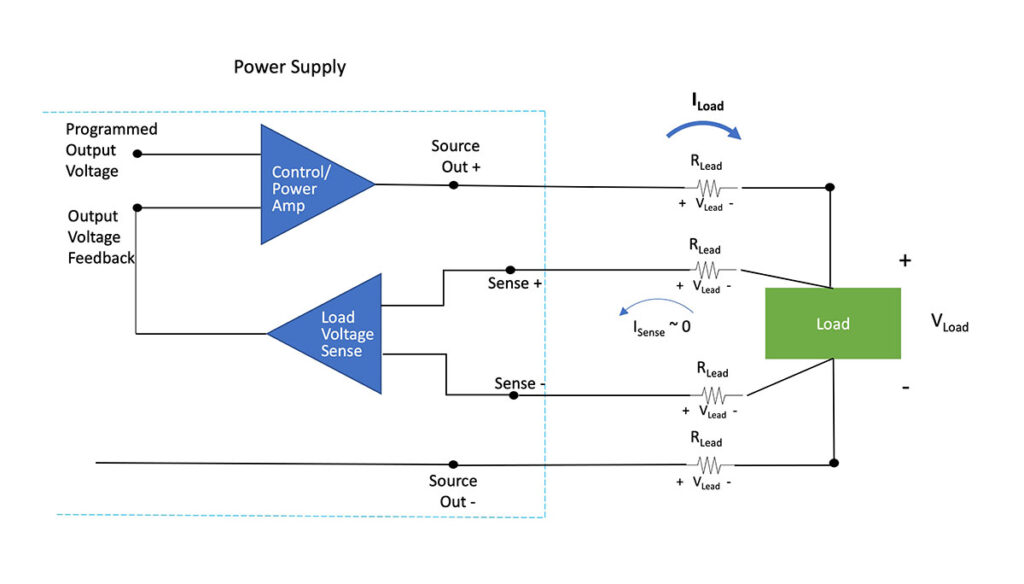 Figure 1. DC power supply with remote sensing to ensure the voltage at the load is the programmed output voltage
Wiring methods
While using remote sensing compensates for the voltage drop across the test leads and the resultant reduced voltage across the load, there are limitations to the magnitude of the voltage drop across the test leads for which the power supply can maintain its accuracy. For the PSI 10200-70 and the EA-PSI 10000 power supply family, the maximum total voltage drop in the leads must be less than 5 % of the nominal output voltage.
If the supply’s output voltage is 24 VDC, then the maximum voltage drop in the lest lead wires should not exceed 1.2 V. Thus, keep test leads as short as possible and select a wire size that both meets safety standards and minimizes the voltage drop across the wire. Following those suggestions will ensure the power supply can accurately source the load.
Minimizing circuit noise and instability due to remote sensing can be a more challenging task. Test engineers may have to try alternate wiring configurations depending on the capacitive and inductive characteristics of the test leads and the load
Keeping the source leads and sense leads separate for a primarily resistive load is one such example. Use twisted wire for the sense leads to minimize the loop area so that an external magnetic field, such as a motor, cannot induce a voltage in the leads. See Figure 2 below.
Remember that an induced voltage from a magnetic field is V = ∫B∙dA
Since the input impedance of the Load Voltage Sense circuit is high, small amounts of external electrical noise on the Sense input could create an error voltage. Use shielded twisted pair wire to eliminate effects from electrical sources of interference.
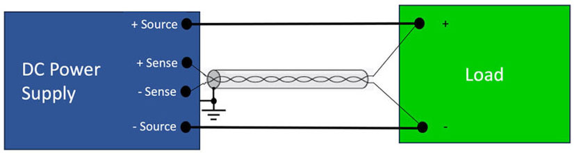
Figure 2. One option for wiring the remote sense leads uses shielded twisted pair wire
Suppose a load has a more complex input impedance. In that case, an alternative wiring scheme may be required to eliminate the potential for oscillation starting in the sense circuit and propagating into the source output.
Recall that a test lead such as a coaxial cable is a distributed RLC network. Even though we are discussing programmable DC power supplies, the supply-load circuit is a complex impedance network. Step changes in program voltages and external noise can induce oscillation on the DC power lines.
Placing each sense wire adjacent to its corresponding source wire can eliminate the potential for an oscillation condition. In some cases, adding capacitance across the load helps to eliminate oscillation.
You may have to experiment with the remote sensing configuration that ensures the most stability for your specific power supply-load circuit.
Challenge: Instrument warm-up
When energized, all instruments require a warm-up time to allow the electronics to achieve thermal equilibrium. Instrument stability and accuracy is specified following a warm-up period. For example, most EA power supplies typically require a 30-minute warm-up to achieve specified accuracy.
Do not overlook this detail! Most EEs know the need to allow an instrument to warm up but often forget about this detail. If a power supply is not allowed to warm up, its initial output will not necessarily be within specification.
Summary: Assess all the factors affecting accuracy in a power supply-load circuit
Both the DC programmable power supply specifications and the supply’s wiring configuration in the circuit affect how accurate the delivery of a load voltage is in a power supply-load circuit. With these reminders, EE’s can get the best accuracy out of your power supply. EA Elektro-Automatik can help with both DC power supply selection and making optimum connections to loads. Contact EA at sales@elektroautomatik.com.