Why Bother with Remote Sensing in DC Power Supplies?
August 21, 2023 | Topics: Power Supplies, Remote Sensing
Avionics electronics, automotive electronics and other power electronics circuitry require accurate calibration of sensing circuits. For example, inaccurate calibration of an automotive battery monitoring circuit could either prematurely shut down or allow excessive discharge of the battery. The inaccurate calibration could eventually reduce EV travel distance or allow the battery to discharge to an unsafe level.
Proper calibration of this type of circuitry requires that the DC programmable power supply voltage to the monitoring circuit be known to a level of precision required for the application. This means the voltage applied to the circuit-under-test must be both a monitored and a known quantity. No matter how accurate the output of the DC power supply is, you cannot guarantee that its output voltage is the voltage applied to the load, the circuit-under-test.
Why is that? The answer is that voltage drop due to current through the lead wires reduces the voltage applied to the load. Even though wires have very low resistance, a reasonably-sized load current combined with a long wire run can generate a non-negligible voltage drop. The total voltage drop is doubled since there is both a supply wire and a return wire of the same length.
To solve this problem, power supplies have remote sense detection circuits that monitor the voltage at the load and feed the voltage back to the power supply. The power supply then raises its output to compensate for the voltage drop across the lead wires.
Ready to Get Started? Request a Quote
What is Remote Sensing?
Remote sensing in DC power supplies refers to a crucial feature that enables accurate voltage regulation, especially in applications with long cable lengths or voltage drops. Essentially, it’s a method to compensate for voltage losses by measuring the voltage directly at the load terminals rather than at the power supply terminals. By doing so, remote sensing ensures precise voltage delivery to the load, regardless of variations in line resistance or cable impedance. This technology plays a pivotal role in maintaining stable and reliable power output, particularly in sensitive electronic systems where voltage fluctuations can lead to performance issues or component damage.
The reality of supplying voltage to a load
Let’s look at a specific situation to determine the voltage across the load when the DC programmable power supply uses just two wires, known as local sensing, because the control circuitry monitors the voltage at the power supply’s output terminals. Then we will look at the situation when the power supply uses remote sensing, monitoring the voltage at the load.
Figure 1 shows a DC power supply applying 48 V to a load that draws 20 A. The wiring to the load is 12 AWG gauge copper with THWN insulation, which has a maximum current carrying capacity of 25 A. The resistance of the wire at room temperature is 0.00162 Ω/ft. With 10 ft of wire between the test rack and the load, the voltage drop across each lead wire is 0.324 V. The total voltage drop across the two lead wires is 0.748 V. Thus, the voltage across the load is not 48 V, the power supply output, but 48 V – 0.748 V or 47.252 V. The error in the applied voltage is 1.6% due to the voltage drop across the lead wires. That is an unacceptable error for many military/aerospace and automotive applications.
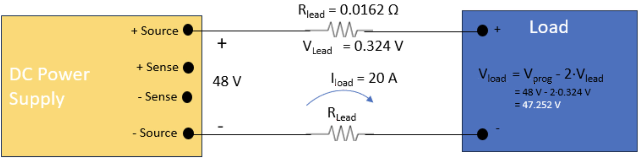 Figure 1. Voltage at the load is lower than the programmed voltage due to voltage drop across the test leads.
The remote sensing solution in DC Programmable Power Supplies
Let’s look at the same load circuit shown in Figure 1, but now we will use remote sensing. Figure 2 gives a little more detail on the power supply circuit and shows remote sense inputs connected to the load. The remote sense circuit is a high-impedance voltage measuring circuit that monitors the voltage at the load.
The high-impedance measurement circuit draws a negligible amount of current from the load. It feeds back the voltage drop across the load, and the power supply control circuit causes the power supply output to increase until the voltage at the load is the programmed supply voltage. Figure 2 shows the output at the power supply terminal and the voltage at the load. Remote sensing eliminates the error in the voltage applied to the load caused by the resistance of the test lead wires.
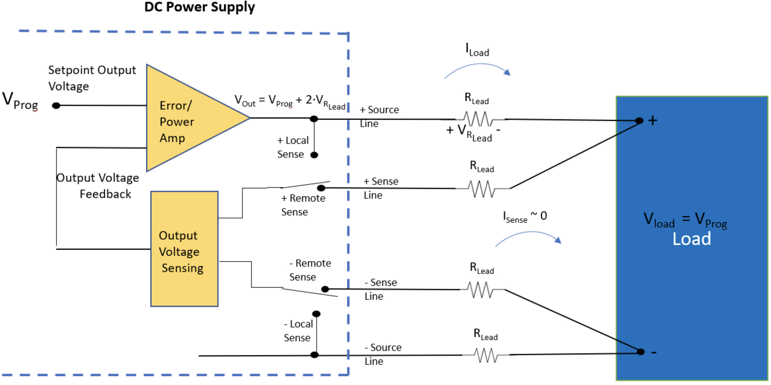 Figure 2. Remote sensing ensures the voltage at the load is the programmed voltage.
Wiring the remote sense circuit for protection from inductive and power source loads
How do you protect the remote sense circuit from an inductive load that can apply back EMF to the power supply? An inductive load, when de-energized, returns stored energy to the circuit with the opposite polarity of the voltage delivered by the power supply. Similarly, suppose a power supply is charging a battery. In that case, the battery will discharge into the power supply if the DC power supply drops its voltage below the voltage of the battery. Both the back EMF from the inductor and the discharge voltage from the battery apply energy to the power supply, damaging the power supply.
A pair of diodes can protect the power supply from the applied energy. However, if remote sensing applies an accurate voltage to the load, the remote sense circuit also needs to be protected from both types of loads.
Figure 3 provides a recommended remote sense wiring method that protects all power supply lines from energy applied to the DC programmable power supply. The one drawback is that the + sense lead is no longer at the load and cannot compensate for the voltage drop of the series diode. Use of this configuration requires characterizing the voltage drop of the series diode at typical load currents and adding the diode voltage drop to the DC power supply’s programmed output voltage setting. Using this wiring configuration and characterizing the series diode both protects the power supply and ensures that the voltage at the load will be the programmed voltage.
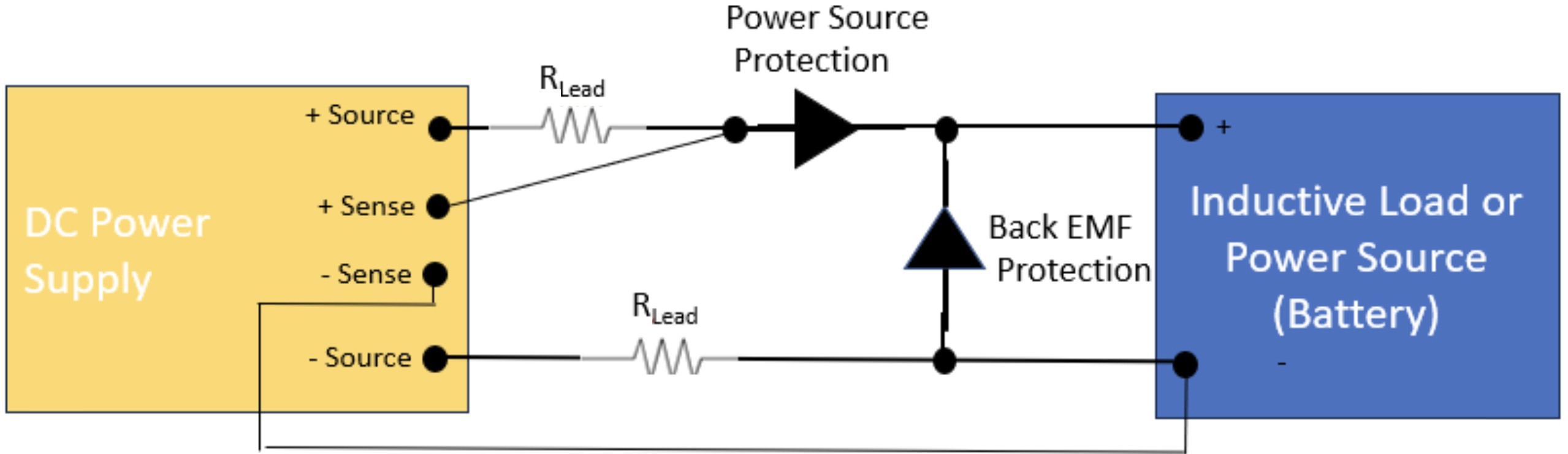 Figure 3. Remote sensing for inductive loads or power sources
Benefit from remote sensing without creating potential oscillation in the DC programmable power supply
The voltage sensing circuit uses a high input impedance voltage measuring circuit. Noise on the sense lines can create detectable perturbations, which get amplified and transmitted to the power supply control circuit. The noise on the control circuit can cause a ripple on the power supply output. If the fluctuations are large enough, they could cause the power supply to oscillate, which can potentially damage the load and the power supply.
Avoid this condition by using proper wiring technique to keep as much noise as possible out of the sense leads. Shield the sense leads to keep EMI out. Also, use twisted pair wire to keep a magnetic field from inducing a voltage in the loop area of the sense lines. Keep the sense lines separate from the power source lines. The DC current in those wires can induce a magnetic field in the loop area of the sense lines. Figure 4 illustrates the most common solution when using sense lines.
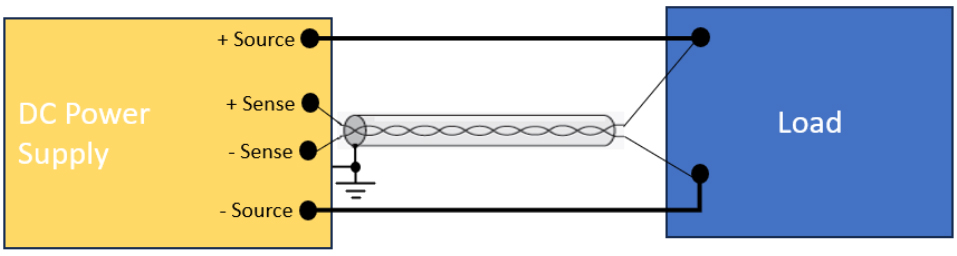 Figure 4. Proper wiring for the remote sense lines
Remote sensing guarantees the correct voltage is applied to the load
Remote sensing provides the accuracy needed when supplying a DC voltage to a load. Using the recommended wiring configurations will avoid canceling out the benefits of remote sensing.
All EA Elektro-Automatik (EA) DC programmable power supplies have remote sensing. EA programmable power supplies can accommodate voltage drops in the test leads up to 5% of the nominal applied voltage, a level superior to other manufacturers’ DC power supplies. Learn more about EA’s remote-sensing power supplies at www.eapowered.com.