
This website uses cookies so that we can provide you with the best user experience possible. Cookie information is stored in your browser and performs functions such as recognising you when you return to our website and helping our team to understand which sections of the website you find most interesting and useful. See our privacy policy.
News
Mistakes to Avoid When Integrating a Battery Test System
Test systems should be designed in a way to recover the energy locally and utilize the inherent benefit of electric vehicles to share charge and discharge energy on a testbed level.
Russ Gaubatz, EA Elektro-Automatik | December 1, 2023
It’s not easy to configure a battery cycle test system for EV batteries and similar high-power batteries. Many components, such as contactors, power supplies, cyclers, data acquisition and sensors, need to be made into a system using software and challenging connections. Getting it wrong could increase costs, disrupt production, or possibly injure or kill workers. This article covers the mistakes that engineers sometimes make when integrating a battery test system.
Manufacturers can build the system themselves, hire an integrator, or buy a turnkey system. Each of these has pros and cons.
If the manufacturer has experts on staff, then integrating the system internally saves money. However, it will consume time in research and troubleshooting and run the risk of mistakes. Even experienced engineers don’t know how the components will work together until they plug them in. And many manufacturers don’t even have experienced engineers on staff. In addition, many executives worry about safety issues if the company is integrating a system themselves. Also, with new equipment and innovations comes the risk of inexperience with the latest integration knowledge.
Professional integrators are staffed with experts, but they are expensive. An integrator will charge for each change. Pity the manager who gets invoiced each time a programmer flies in or remotes in to change a single line of code.
Turnkey systems may require a tweak or two to fit proprietary equipment or tests, but the engineer will have confidence that the components play well together. While running the risk of being locked into one supplier, integrating with internal resources or an integrator allows the manufacturer to get the desired components and system.
Some turnkey test systems suppliers are willing to customize things like the communications bus and spread the integration costs across multiple orders. The user gets the configuration they want for a reasonable cost.
Whatever the approach, engineers should avoid common mistakes.
Poor Component Selection
A common mistake is selecting unsuitable components for the test system, or ones that won’t perform reliably. A good example is a contactor. Sometimes, engineers choose inexpensive contactors to save money. The risk here is that operators may have to replace the contactors every few months, disrupting testing.
Some contactors have the ability to send a signal reporting their status so operators know if a contactor has failed to open or failed to close. This is a feature that is worth the extra cost. In the event that the circuit is exposed to higher power than specified, the energy may cause the contacts to weld together. This means the circuit remains live and connected to the battery. In turn, this may lead to situations that damage the test system or pose danger to people.
Other examples include underspecifying the size of the cables and connectors. In the event of an overcurrent, the cables and connectors could melt and start a fire. Melted connectors are not uncommon in battery test systems. Even bolted connections require careful implementation. If the connections are not tightened to the proper torque spec, heat points could eventually melt the cables or cause high resistance points which could skew test results.
Overlooking Safety Features
Many engineers never think about putting e-stops in the system. If a battery starts going into a thermal event, the operator needs an e-stop to be able to immediately shut down the system. Another way to handle battery thermal events is with a temperature sensor. The sensor signals that the battery temperature is going up at a certain rate, and control software shuts down the system automatically. It would be a mistake to leave out either of these safety features.
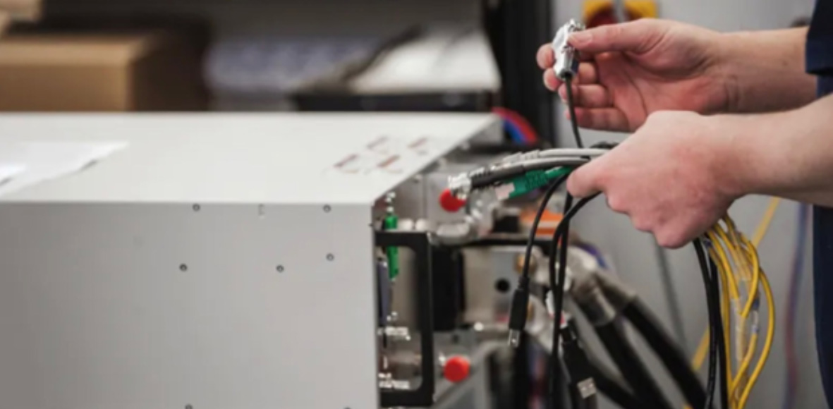
Many components must be integrated successfully to build a battery test system. (Image: EA Elektro-Automatik).
Another important safety consideration is equalizing the voltage before connecting to a battery. Failure to equalize could create a significant arc, which wears contacts and could be an electrical hazard. Potentially, it could cause equipment damage, personal injury, or component failure.
The ability to equalize voltage can be achieved in two different ways. Some systems pre-charge the instrument to a voltage approximately equal to the battery voltage. Another approach is precharge resistance. There is a contactor on the negative line and two contactors on the positive line. On one positive contactor, the circuit has a resistor that slows the current inrush. Otherwise, a sudden inrush could damage system components. After the voltage has a chance to equalize at a slow rate, the system closes the second positive contactor and opens the connector with the pre-charge resistor.
A pre-charge approach requires the system to measure the voltage on the device under test, match that voltage in the test system, and then close the main contactors. Some companies make this a manual process. A technician uses a multimeter to measure the battery before they connect it. Then the technician sets the power supply voltage and turns on the output. After that, the technician goes back to the battery to re-measure. When the voltage is equal, they flip a switch to close the contactors. If technicians skip a step, or if they don’t notice that the voltage is off by a digit, they could damage the test system.
Details matter when it comes to safety. For instance, the engineer who is integrating the system may not label the connections clearly. A technician might connect the negative to the positive and the positive to the negative. If the voltage is -110 volts on the battery and +110 volts on the test system, then the total error is 220 volts. Such a significant level of voltage can be very damaging. The solution is to engineer a check for reverse polarity into the test system.
Overlooking the Impact of Heat on Energy Costs
There are many considerations for selecting programmable power supplies and electronic loads. Foremost is which type to buy. For testing large batteries, a bi-directional regenerative power supply is the usual choice. These instruments both supply and draw power.
Some manufacturers are tempted to use simple power supplies for charging a battery and use linear loads or electronic loads to apply a load to the battery. These are less expensive; however, they emit heat that increases air conditioning costs. Sometimes, they’re ducted outdoors using noisy fans.
In contrast, a regenerative power supply captures the power drawn from the battery and returns it to the grid. Not only does this lower energy bills, but it also enables manufacturers to meet green initiatives. A regenerative power supply usually pays for itself via energy savings in a few years, unlike a linear load that uses resistors to convert electricity into waste heat.
Failure to Use a Modular Design
It may seem fine to mix and match brands of equipment, but engineers must consider balancing outputs and loads across the power supplies. If one regenerative power supply fails, then the other power supplies in series should pick up the output/load and share it equally or all should stop in order not to overload any single power supply.
Some power supply manufacturers design each power supply to use a shared bus so units in a rack can communicate with each other and share resources equally. The control software needs to notice if the remaining power supplies are overtaxed. For example, say the operator is discharging a battery at 100 A using two 50 A loads. If one of the loads fails, then the remaining electronic load is absorbing 100 A, and it may not be rated for that. The software should notice the problem and shut down the test system to prevent damage.
One advantage of a modular design is reliability. If one electronic load or power supply fails, battery testing does not need to stop until a replacement unit arrives. Instead, the remaining equipment can continue operation at a lower power rating. Many manufacturers may also keep an extra unit on site to switch out any failed power supply immediately. This avoids the need to wait for a service tech to arrive or units to be returned from repair.
Not Considering Space Requirements
A final consideration is power density. Production floor space is precious. As battery power capacity increases, the number of test racks increases. If the space is unavailable on the plant floor, the company faces the costly prospect of rearranging the production line. Even in a test lab, space is limited. Exits should be easy to access in case of an emergency. Engineers should strive for the fewest number of racks needed to accomplish the testing.
Here is another advantage of the modular systems mentioned above. Modular systems have the ability to easily accept power supplies as power and current requirements grow, as long as max voltages stay the same, saving costs.
Avoiding integration pitfalls will help manufacturers test batteries safely and get the most out of their investment in test equipment.
This article was written by Russ Gaubatz, Senior Applications Engineer, EA Elektro-Automatik (Novi, MI).

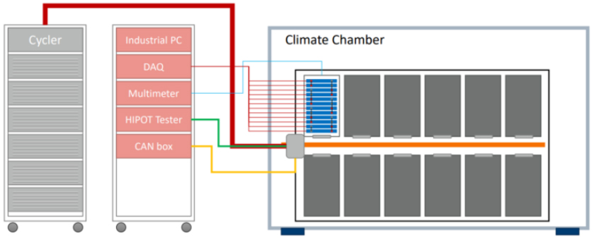
An example of a turnkey battery test system, the EA-BTS 10300 Series from EA Elektro-Automatik includes software, high power density, and modular design plus bidirectional, regenerative operation (Image: EA Elektro-Automatik).