How to Combine a Function Generator With a Power Supply for Efficient Testing
May 03, 2022 | Topics: Battery Test, Function Generator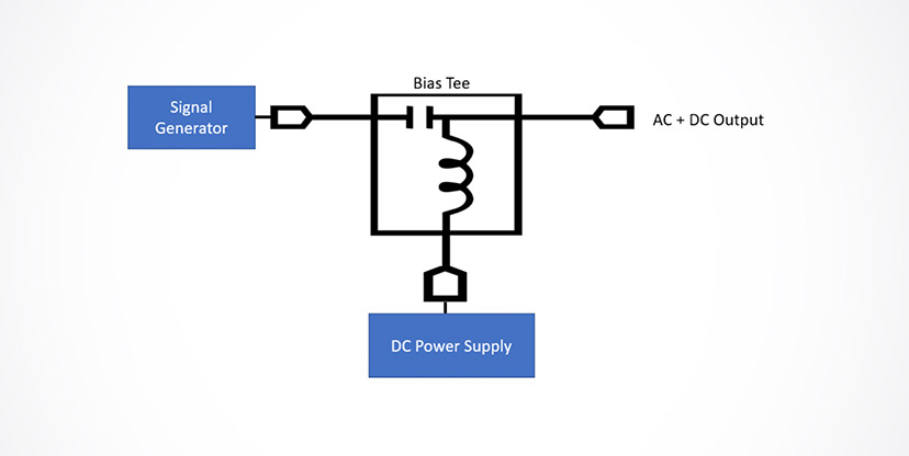
Function generators and power supplies are two of the most crucial tools in your toolkit. Either piece of test equipment can support a wide range of projects and activities. You can further expand these test instruments’ capabilities by combining your power supply with a function generator.
But what does a function generator do, exactly? Learn the answer to this question below, and explore the benefits of pairing your machine with a reliable power supply.
Ready to Get Started? Request a Quote
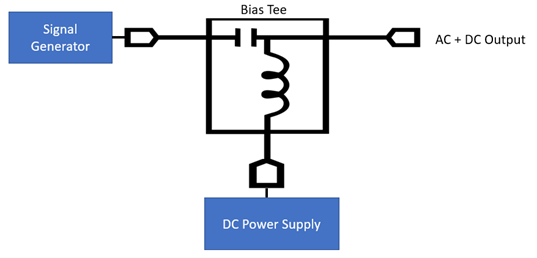
Figure 1. A bias Tee combines a signal generator output with a DC power supply output, but is power limited
What Does a Function Generator Do?
A function generator is an electronic device that produces a variety of electrical waveforms over a wide range of frequencies. The standard waveforms include sine waves, square waves, triangular waveforms, and more. Also known as an arbitrary waveform generator, these machines test different signal conditions that an electronic device might encounter during its operation.
It’s possible to adjust a function generator’s settings to determine how a device or component holds up in various conditions. You can manipulate factors like frequency (in MHz or KHz), amplitude, and bandwidth. Additionally, you have the option to create simple square waveforms or run tests with complex waveforms.
The function generator has numerous applications. You can use it for everything from simple circuit debugging to complex system analysis. They allow you to test the functionality and performance of electronic components under controlled conditions by generating precise signals and pulse waveforms.
Built-in function generator for AC + DC signal generation
The best solution is to do what EA Elektro-Automatik does which is build the function generator into a power supply or a load. Then you do not have to worry about protecting a low-power signal generator from a source of high power. In fact, there is no low power hardware to protect as the EA function generator is entirely firmware.
The function generator can generate sine waves, triangular waves, rectangular waves, ramps, as well as custom waveforms. You can use these waveforms to:
- Test a circuit’s susceptibility to power line noise immunity by adding a 60 (50) Hz signal (and harmonics) onto a DC voltage representing the DC rail lines
- Test a circuit’s response to varying voltage rail ramp-up rates
- Determine the range of rail voltages over which a circuit will remain powered
- Simulate voltage spikes to test a circuit’s level of protection from voltage transients
- Test a circuit’s susceptibility to a kHz custom noise signal representing the output of a switching power supply.
These are just some examples of how an arbitrary waveform generator built into a DC power supply can conveniently enable a test engineer to more thoroughly test a circuit or a product. More extensive testing improves product reliability.
EA’s built-in function generator has even more capability. The function generator has the capability to create I-V curves to simulate devices such as solar cells, batteries, and fuel cells.
Simulating a solar panel or a solar panel array for inverter testing
Let’s simulate a solar panel. We need to create an I-V curve for the solar panel. First let’s review how a solar cell works so we can understand what the function generator will define for the solar panel, a set of connected solar cells. A solar cell model consists of a current source which represents the solar light creating current, a p-n junction represented by a diode, and resistances in series with and in parallel with the p-n junction. Photons impinge upon electrons in the p-n junction and provide sufficient energy to enable the electronics to transition to the conduction band. The electric field that builds up turns on the diode, and current flows to the output of the solar cell. Figure 2 shows a simple model for a solar cell.
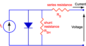 Figure 2. Circuit model for a solar cell
The series and shunt resistances represent the losses in the solar cell. The series resistance represents the resistance of the solar cell semiconductor material and the resistance of its metal contacts. The shunt resistance represents the insulation resistance defined by the leakage current through the p-n junction. Having a lower series resistance and a higher shunt resistance increases the efficiency of the solar cell.
Based on this model, the solar cell has an I-V characteristic as shown by the red curve in Figure 3. The p-n junction exhibits an inverse diode characteristic. The key parameters that define the curve are the solar cell’s short circuit current, ISC, its open circuit voltage, VOC, and the point where the solar cell’s power output is a maximum, the maximum power point, MPP. The ISC and the VOC are the maximum current and voltage that the solar cell can generate. VMP and IMP, as shown by the blue curve in Figure 3, represent the I-V parameters of the maximum power output that the solar cell can generate. Operating the solar cell at its MPP ensures maximum performance from the solar cell and is the target operating point.
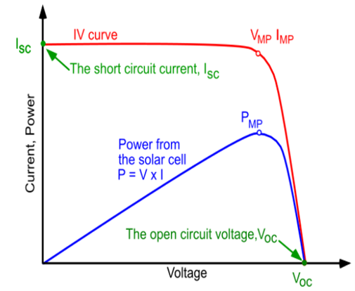 Figure 3. I-V characteristic of a solar cell (red curve) and the power output (blue curve)
The built-in function generator of the EA Elektro-Automatik instruments, such as the PSB bidirectional DC power supplies, makes it easy to create the solar cell I-V curve. The function generator requires four parameters: the open circuit voltage, the short circuit current, and the maximum power point current and voltage. Figure 4 shows the setup screen which will create the I-V curve.
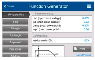 Figure 4. Function generator setup screen for solar cell simulation.
Test engineers can use the simulated solar cell to test solar cell inverters and how well they can track the maximum power point of the solar cell or solar panel. The function generator enables testing of an inverter’s efficiency in compliance with standard EN 50530 Overall efficiency of grid connected phototovoltaic inverters. The EN50530 test mode allows determination of inverter response to changes in the maximum power point. In addition, the test mode allows inputs to change irradiance on the solar panel and changes in its surface temperature. Both parameters affect solar cell output.
Using a test rack of as many as 64 PSB 30 kW supplies, a test engineer can simulate a 1.92 MW solar farm. This allows complete testing of solar inverters for power distribution applications.
Simulating a battery for testing a battery-operated system and its charger
A second example of an application for the function generator’s XY generator is the simulation of a battery. Figure 5 illustrates a simple model for a battery. The model uses an ideal voltage source representing the battery’s open circuit voltage and an internal resistance representing the electrochemical and the electronic resistances in the battery. As the load current increases, the output voltage of the battery declines due to the increase in the voltage drop across the internal resistance. A test engineer can determine how a load, such as an electric vehicle motor, responds to the drop in battery voltage when the motor increases its current draw.
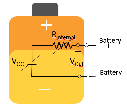 Figure 5. Simplified model of a battery using an ideal voltage source and an internal resistance
Using the function generator in the ELR electronic load, the ELR load can simulate a battery for charger testing. The load can determine how well a charger can supply a high current output for fast charging a battery. Also the simulated battery load can test the chargers ability to safely trickle charge the battery when 100% charge has been achieved.
Benefits of Combining a Function Generator With a Power Supply
A signal generator provides robust modulation capabilities. It becomes even more robust when you combine it with a power supply. External supplies don’t act as amplifiers. The machines don’t increase the output signal of your arbitrary function generator, either. They ensure the device you are evaluating receives consistent voltage throughout testing.
Here are the benefits of pairing the two testing devices:
Enhanced Testing Capabilities and Precision
Combining a function generator with a power supply significantly enhances your testing capabilities. The function generator provides the necessary signal inputs. The power supply ensures that the device under test (DUT) receives a stable, consistent voltage.
You can’t effectively simulate real-world conditions if the DUT is receiving inconsistent power. An external power supply remedies this barrier to analysis and helps you create realistic tests.
Flexibility in Testing Various Electrical Components and Systems
You can test a wide range of electrical components and systems. Whether you’re working on simple resistive loads, complex reactive circuits, or high-powered devices, this combination offers the flexibility needed to adapt to different testing scenarios.
You can pair a high-frequency pulse generator with a DC power supply to test the calibration of sensitive circuitry. You can easily transition to impedance testing using the same equipment to evaluate whether a fault current will activate circuit protection. These are just a few examples of how a function generator and power supply promote more comprehensive testing.
Improved Efficiency and Accuracy in Test Setups
Integrating a function generator and a power supply can streamline your test setups. This equipment can cut down on test setup time, allowing you to conduct a more complete analysis of your designs. This efficiency translates to faster troubleshooting, quicker development cycles, and a more productive testing environment.
You’ll need to pair your function generator with a high-quality power supply to enjoy efficiency gains. Elektro Automatik (EA) Powered offers a variety of solutions that are ideal for pairing with your function generator. Our autoranging DC power supply can generate electricity in a preset frequency range to test several device functions.
We also offer a bidirectional DC power supply. It promotes optimal efficiency while minimizing waste. Explore these and other options at EA Powered. You can also book a free online demo to learn more about the capabilities of our power supply solutions.
High Voltage Function Generator: Key Considerations
High voltage testing is essential for evaluating your design’s performance and reliability. Before selecting a function generator, it’s crucial that you understand your specific testing requirements and the demands of your scenarios. You might consider variables such as voltage range, current capacity, and the waveform characteristics needed to accurately simulate operating conditions.
You’ll also need to make safety a priority at every phase of scenario planning and testing execution. While you want to push the limits of your designs, it’s important that you take steps to protect your team from the dangers of electrical circuit testing, too. Here are a few best practices to promote safety while also keeping your tests viable and realistic:
Use Proper Insulation
Ensure that all connections and test leads are properly insulated. Doing so will help prevent accidental contact with high-voltage wiring.
Establish a Minimum Safe Distance
Determine how far away your personnel should be from the function generator during testing, and educate your team on these established safe distance thresholds. Additionally, have everyone follow these guidelines during all simulations, regardless of how much or little voltage is involved.
Use Protective Equipment
All team members should wear personal protective equipment (PPE) during testing. Some common PPE items are safety glasses and gloves.
Purchase High-Quality Machines
EA Powered manufactures a line of robust testing equipment. All our devices are equipped with the latest safety features. Our power supplies, oscilloscopes, and function generators feature user-friendly designs and overload protection to keep your team safe from accidents.
Follow Manufacturer Guidelines
Adhere to the safety guidelines outlined in your function generator and power supply’s user manuals. EA Powered provides detailed user manuals and other educational resources so that your team can acclimate themselves to our equipment.
Step-By-Step Guide to Combining a Function Generator With a Power Supply
Combining a power supply and function generator involves four simple steps, which are as follows:
1. Selecting the Right Equipment
Choosing the right function generator and power supply will streamline the process of combining the two testing devices while ensuring they meet your project requirements. Consider the output range of the machines to make sure that they can provide the necessary voltage and current levels for your tests.
Also, choose a function generator that can produce the specific waveforms required for your testing scenarios. Look behind the current phase of design analysis, and think ahead by selecting a device that can make a wide range of waveforms. The more versatile a function generator, the better value it will deliver.
Ensure that the two devices are compatible with one another and can easily be integrated. Ordering both devices from the same manufacturer is the easiest way to guarantee compatibility. EA Powered offers a wide selection of function generators and power supplies. Our experienced team can help you choose the ideal solution for your intended use case.
We will learn more about your project demands and the type of equipment you are testing. Our team can then make a personalized recommendation. We also offer free online demos so you can see the capabilities of our devices.
2. Setting Up the Equipment
After your equipment arrives, it’s time to connect the function generator to the power supply. Check that both systems are powered off before making any connections, and use the appropriate cables to connect the output of the function generator to the input of the device under test.
Next, connect the power supply to the device under test. When you do this, make sure that the voltage and current settings are configured correctly.
EA Powered provides detailed instructions with all of our equipment. Refer back to the user manual if you encounter any concerns or questions while connecting the power supply and function generator. You can also contact our team for personalized assistance.
3. Running Tests
After you’ve configured your devices and verified all connections, it’s time to run your first test. Turn on the power supply and function generator. Use an oscilloscope or multimeter to monitor the output signals and voltage levels. Execute your test scenarios and observe how the device responds to different signal inputs and voltage levels.
It’s important to capture relevant data during the evaluation process, paying attention to information like signal waveforms and voltage levels. Note any anomalies you observe as well. You can adjust the function generator’s settings or power supply output to fine-tune the testing conditions.
Keep detailed records of your findings for troubleshooting. You’ll need as much information as possible during the next phase.
4. Analyzing Results
Now, it’s time to compare the data you’ve gathered against expected outcomes to identify any discrepancies or issues. Examine the waveforms produced during your tests to understand how the device responded to different inputs.
Make necessary adjustments to achieve more accurate results. Repeat additional tests to validate your findings and ensure your design performs consistently. After you are satisfied that your device will consistently perform as designed, you can move on to the next round of testing.
Real-World Applications
You can use your power supply and function generator to perform a plethora of tests and evaluations. One common use is power amplifier testing.
Engineers working on a high-power amplifier need to simulate multiple signal conditions to test the device’s performance. By combining a function generator with a power supply, they can precisely control the input signals and supply voltage, leading to more accurate and reliable results.
Power supplies and function generators are also a staple of the automotive industry. Engineers use them to test electronic control units (ECUs). Analyzing an EC’s function requires simulating complex signal patterns and voltage conditions. A combined function generator and power supply setup enables engineers to replicate real-world driving conditions, enhancing performance and reliability.
Order a High-Voltage Function Generator From EA Powered
Combining a function generator with a power supply offers numerous advantages for efficient and accurate testing. Your team can create more realistic and flexible simulations and mimic real-world environments. Improving the quality and realism of testing conditions can help make your results more reliable and precise.
Ultimately, improving testing capabilities will promote a better consumer experience while also bolstering your company’s reputation. In turn, you can establish yourself as a designer of high-quality, reliable electrical components that exceed expectations.
Are you ready to take your testing to the next level? Explore EA Powered’s range of function generators and power supplies to discover how they can enhance your testing processes. Request a quote from EA Powered or schedule an online demo today.